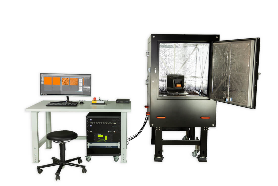
Alphacen 300 – The tip-scanning AFM for heavy and large samples up to 300 mm
Standard AFM system 300 mm x 300 mm sample stage Ideal for samples up to 45 kg
Nanosurf is the market leader for custom developed systems for large and heavy samples. Over the past years our team has built a substantial knowledge base developing these custom stages for various customers.
Utilizing this vast body of knowledge, we have now developed a standard product for large samples up to 300 mm or heavy samples up to 45 kg. The Alphacen 300 reduces the price and the delivery time compared to a custom system.
This is a recording of the demonstration about Alphacen 300, the large sample AFM from Nanosurf. Dr. Christian Bippes, Application scientist conducts the demonstration during which he highlights the features of the Alphacen 300. The Alphacen 300 system can access a sample area of 300 mm x 300 mm. The system is designed to handle large and heavy samples (up to 45kg). During this demo, Dr. Bippes shows how the Alphacen 300 is operated, including sample loading, approach and imaging of a sample surface.
Download the Alphacen 300 brochure
Run automated measurement series
The Alphacen 300 includes powerful automation software that allows the user to preselect the locations of interest, either on an optical image or a stage map, and let the system collect the images with no user intervention.
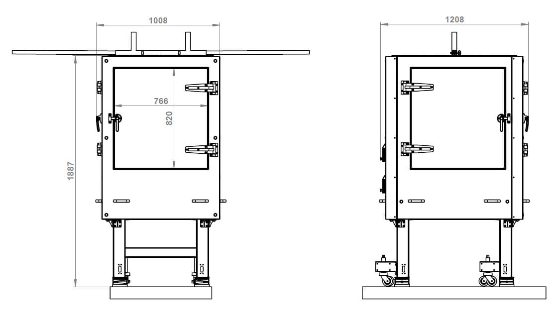
The Alphacen 300 stage allows measurement on every point of a 300 mm x 300 mm sample
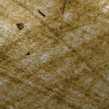
Heavy glass samples
Most large sample AFMs are capable of handling planar samples up to 200 mm, typically geared toward analysis of semiconductor wafers. However, one of the limitations of these systems is the sample weight that they can handle.
Alphacen 300 addresses the need for a standard AFM capable of imaging large and heavy samples with a weight limit of up to 45 kg. The Z-stage travel of 50 mm also allows for imaging of samples that are not thin silicon wafer.
Large, heavy samples are quite commonplace in the optical industry, e.g. in the production of large lenses and semiconductor industry, e.g. assembled cassettes or completed products.
Large samples
The Alphacen 300 AFM system has a sample stage that can move 300 mm x 300 mm in XY and can measure every point on 300 mm sample. On request, the stage can be modified to handle a larger range in X (up to 500 mm).
The XY stage has a resolution of 1 µm and a unilateral repositioning accuracy of 2 µm which allows for precise positioning of the sample under the imaging tip.
The software’s integrated automation feature enables time saving pre-programming of measurement series.
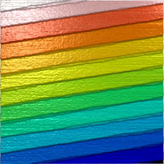
Scan size:
1.5 µm x 1.5 µm
The scan shows step heights of 1.5 nm between the large terraces, and 0.75 nm between the large and small terrace half-steps.
This overview shows which modes the instrument is capable of. Some modes may require additional components or software options. For details, please contact us.
Standard imaging modes
Static Force Mode
Lateral Force Mode
Dynamic Force Mode (Tapping Mode)
Phase Imaging Mode
Thermal imaging modes
Scanning Thermal Microscopy (SThM)
Magnetic properties
Magnetic Force Microscopy
Electrical properties
Conductive AFM (C-AFM)
Piezoelectric Force Microscopy (PFM)
Electrostatic Force Microscopy (EFM)
Kelvin Probe Force Microscopy (KPFM)
Scanning Spreading Resistance Microscopy (SSRM)
Mechanical properties
Force Spectroscopy
Force Modulation
Stiffness and Modulus
Adhesion
Unfolding and Stretching
Force Mapping
Other measurement modes
Lithography and Nanomanipulation
Electrochemical AFM (EC-AFM)
Software
Control software
The control software for Nanosurf AFMs is an intuitive platform made for performing your AFM measurements efficiently and easily. Our Service team and software engineers are constantly developing and implementing new features and enhancements to further improve the user experience. We regularly publish new and improved versions, which you can download for free. You can install the software on as many computers as you wish to analyze your data.
Free lifetime updates: download all software updates for free
All software updates for Nanosurf control software are free of charge. Our software team is constantly working on new features and improvements to make the user experience better, more intuitive and more efficient.
Software features
Automatic/parameter-free frequency tuning based on cantilever characteristics
Simply choose the cantilever you are using, and the system automatically performs the frequency sweep prior to approaching the sample. No manual setting of parameters is required.
Distance measuring tools: measure the distance between points or lines, the height of features, and more
A selection of different measuring tools allow you to accurately measure angles and distances directly on the acquired measurement image.
Determine the distance between two points or between two parallel lines to make very precise measurement (as shown in the video).
Scripting interface: Python package for COM interface
Python API for data acquisition and control of Nanosurf atomic force microscopes
At Nanosurf we realize that leading researchers are often interested in modifying the standard routines of an instrument, or else everyone would be doing the same thing with the same hardware.
Sometimes there are also application-specific routines, the scope of which we cannot predict and program ourselves. This is why we developed the Nanosurf Scripting Interface.
This interface can be used for automation of routine tasks and for creating new experiments. It gives the users full control over our user interface, and some control over the hardware functionality.
The Nanosurf control software publishes its functionality via the COM interface, by running an instance of COM Automation Server. COM Automation Clients can ask the server during the runtime about its functions and access them. These functions can be accessed through most modern programming languages: Python, C++, C#, VBS, Matlab, JS, LabView, etc.
For ease of use, Nanosurf has created a Python API for its COM interface. We chose Python as our API language, because of its ease of use and learning, popularity and universality, and because of number of data and image processing libraries used in academia and industry.
The Nanosurf Python package can be downloaded and installed from PyPI using pip:
See how to take control over the GUI settings in Python. The video shows the most basic actions, like changing the imaging mode, choosing the right cantilever, adjusting image parameters
and the PID settings. See how to automatically find the working frequency, start the approach, start scanning, and save the data.
On-demand webinar on Nanosurf's Python API
In this webinar we introduce the Nanosurf Python API and learn how to control Nanosurf instruments with it. We also briefly touch on the processing of the data, stored in NID files, and look at how to create custom user interfaces.
Additional usability features
Spectroscopy wizard: follow easy steps to set up spectroscopy measurements
One software UI for all scan heads: no additional learning curve if you use multiple Nanosurf AFM systems
Automated deflection calibration
UI layouts for beginners and advanced users
Highly configurable graph area with mode-dependent auto-layout: the software automatically shows the relevant graphs and information
Easy file handling with comfort features: auto apply naming conventions, Windows Explorer integration, image gallery, bulk renaming.